What is an industrial drawing and what is it used for?
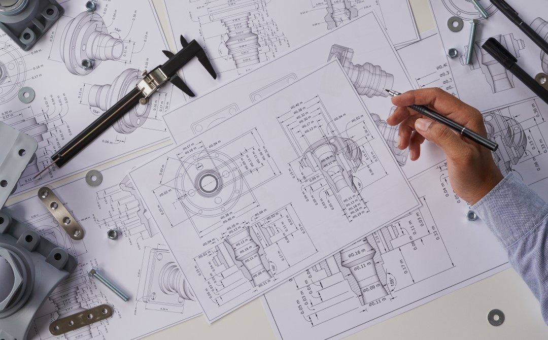
Have you ever had the chance to take a look at an industrial drawing? The amount of information it contains is such that it can be used to perfectly recreate the object, equipment, assembly or product depicted. But you still need to know how to interpret it!
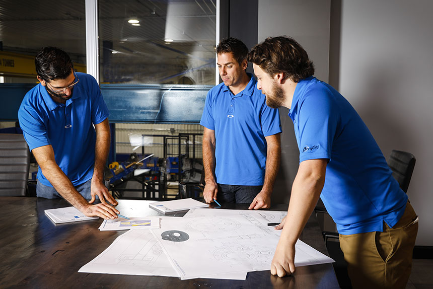
At Omnifab, since we work in both mechanical design and manufacturing, industrial drawing is one of our most precious tools in the realization of industrial projects. It’s the language we use to bridge the gap between our vision and concrete reality.
In fact, it’s our passion for this language that has led us to explain to you, as precisely as possible, what an industrial drawing is.
Definition and role of industrial drawing
An industrial drawing is a technical representation of an object or system, created according to standardized rules, to accurately present its essential characteristics for manufacturing purposes. It serves as a reference for everyone involved in the design and production process. This drawing includes detailed information such as dimensions, shapes, scale, and materials used.
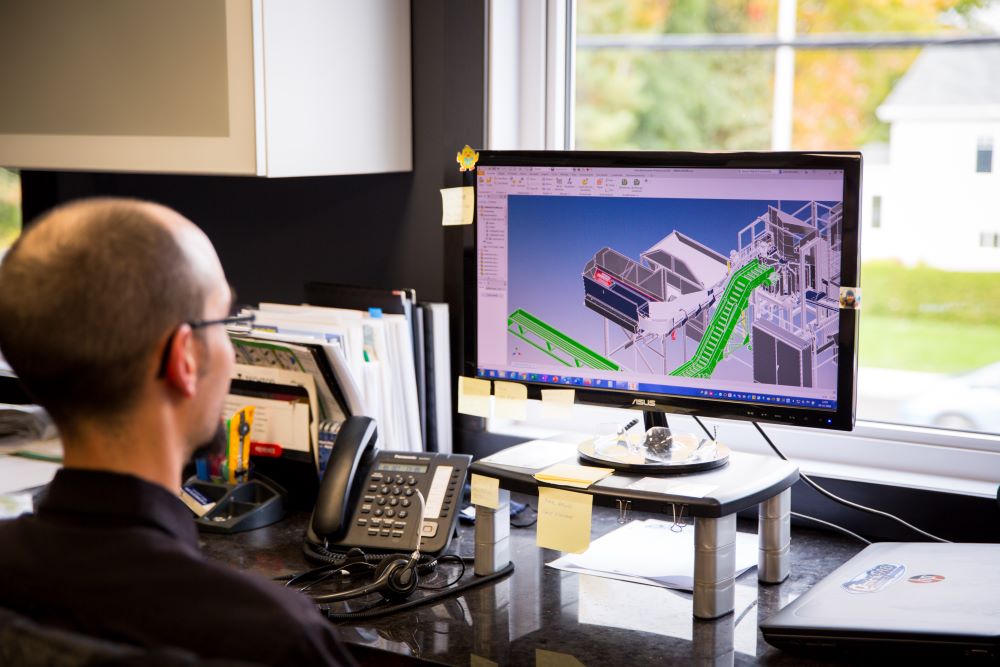
An industrial drawing can be made using computer-aided design (CAD) software (e.g., Inventor, AutoCAD) or by hand, using specialized tools to ensure precision. It must be understandable and interpretable by all project stakeholders, which is why the standards and conventions used are crucial. These standards ensure uniform reading of the drawing, regardless of location or context, thus facilitating international collaboration and standardization in manufacturing.
Who creates industrial drawings?
Industrial drawings are generally developed by professionals specialized in the design, production, and management of technical objects:
- Industrial designers
- Industrial drawing technicians
- Engineers
- Engineering technicians
- Product designers
- Industrial architects
- Production management technicians
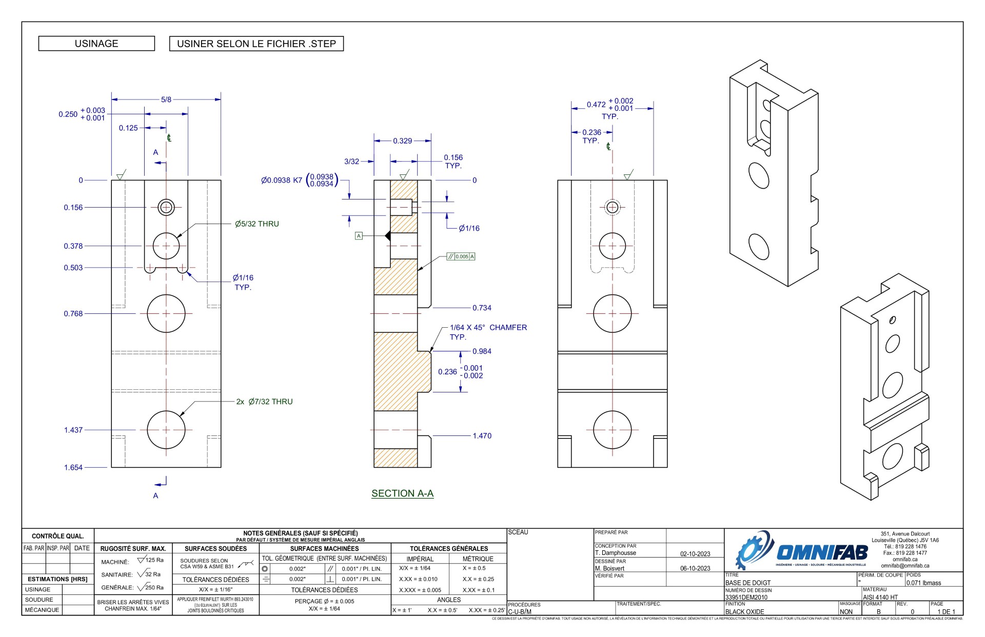
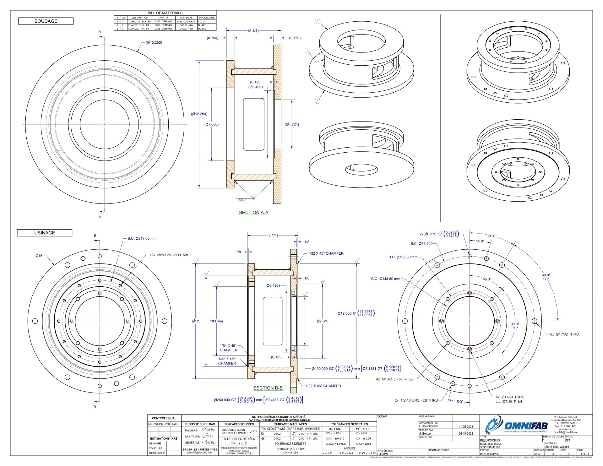
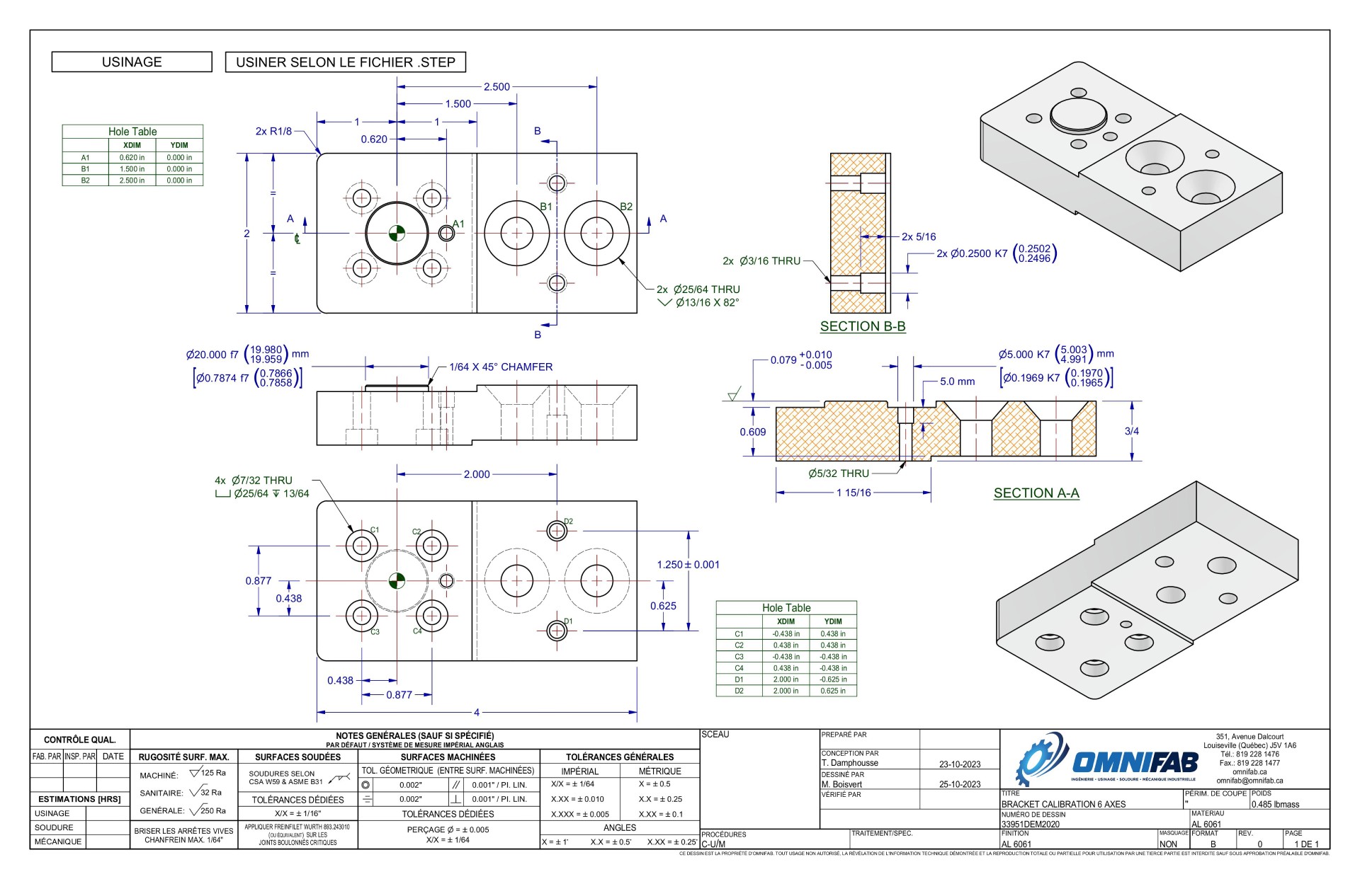
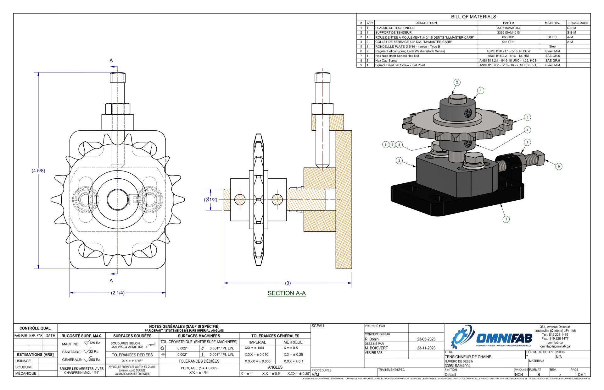
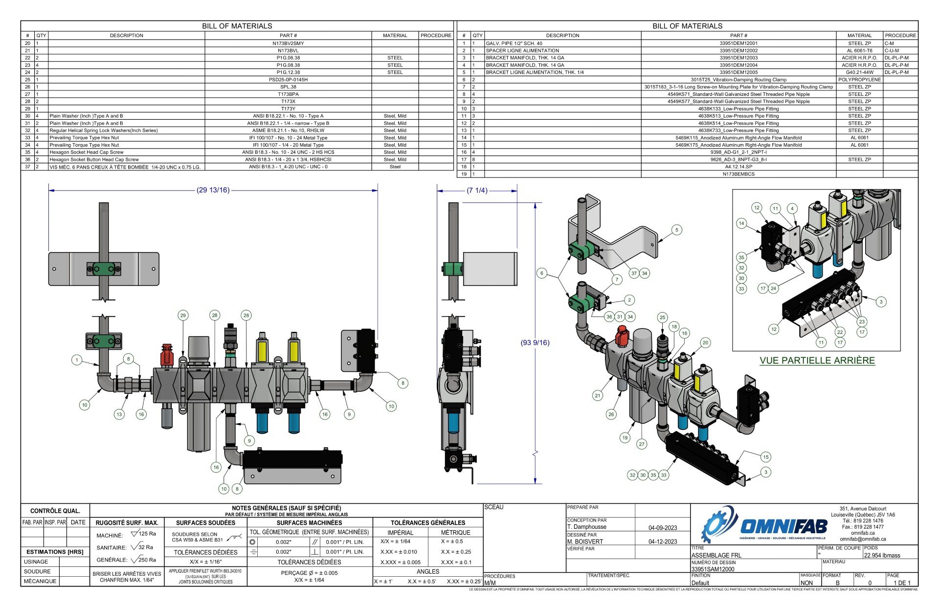
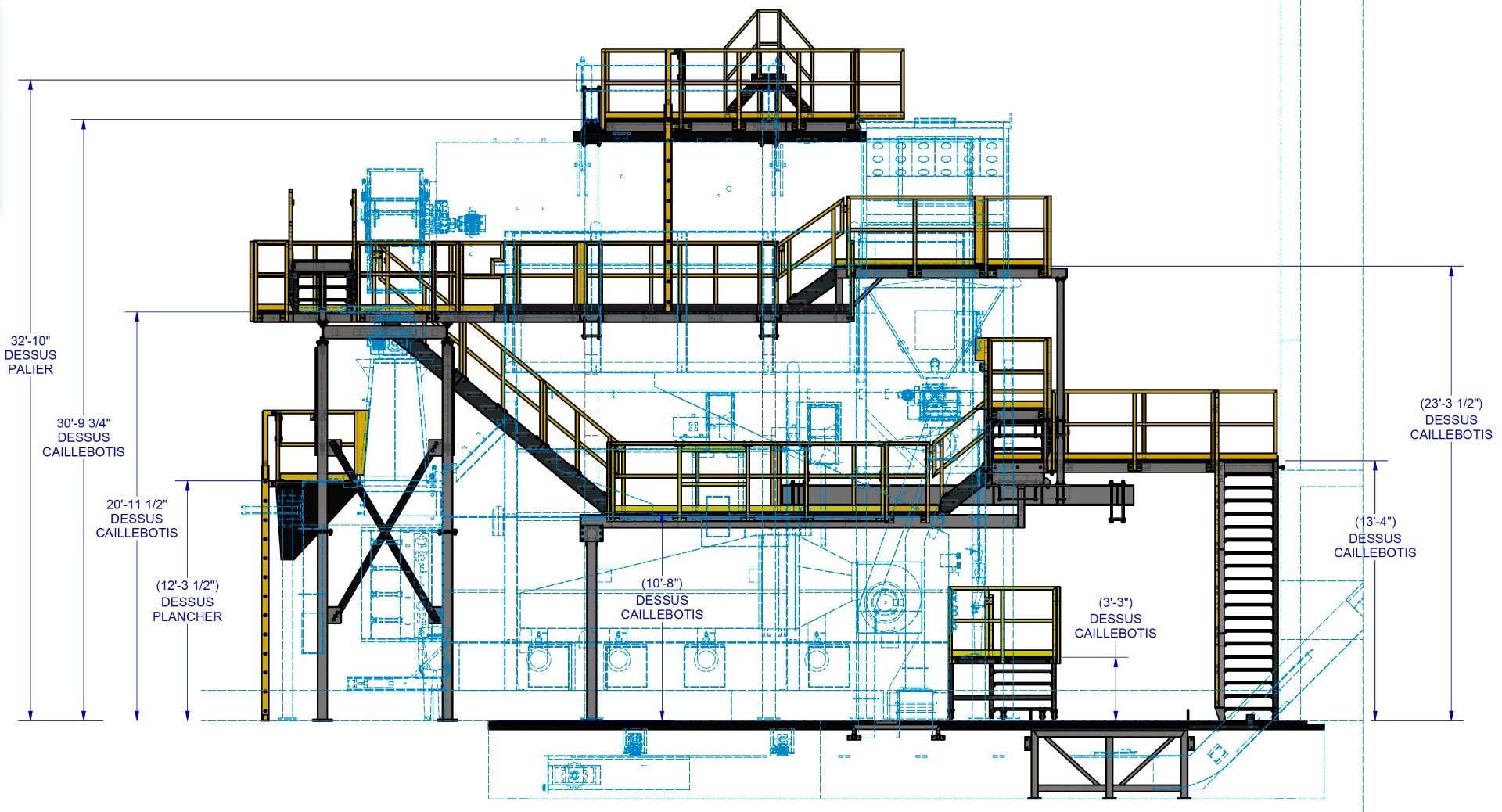
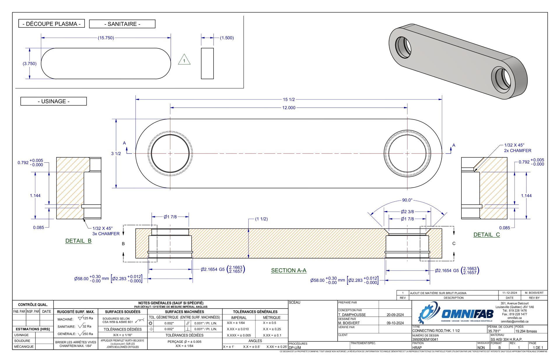
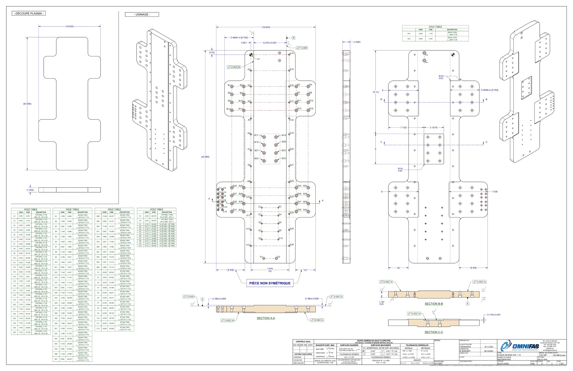
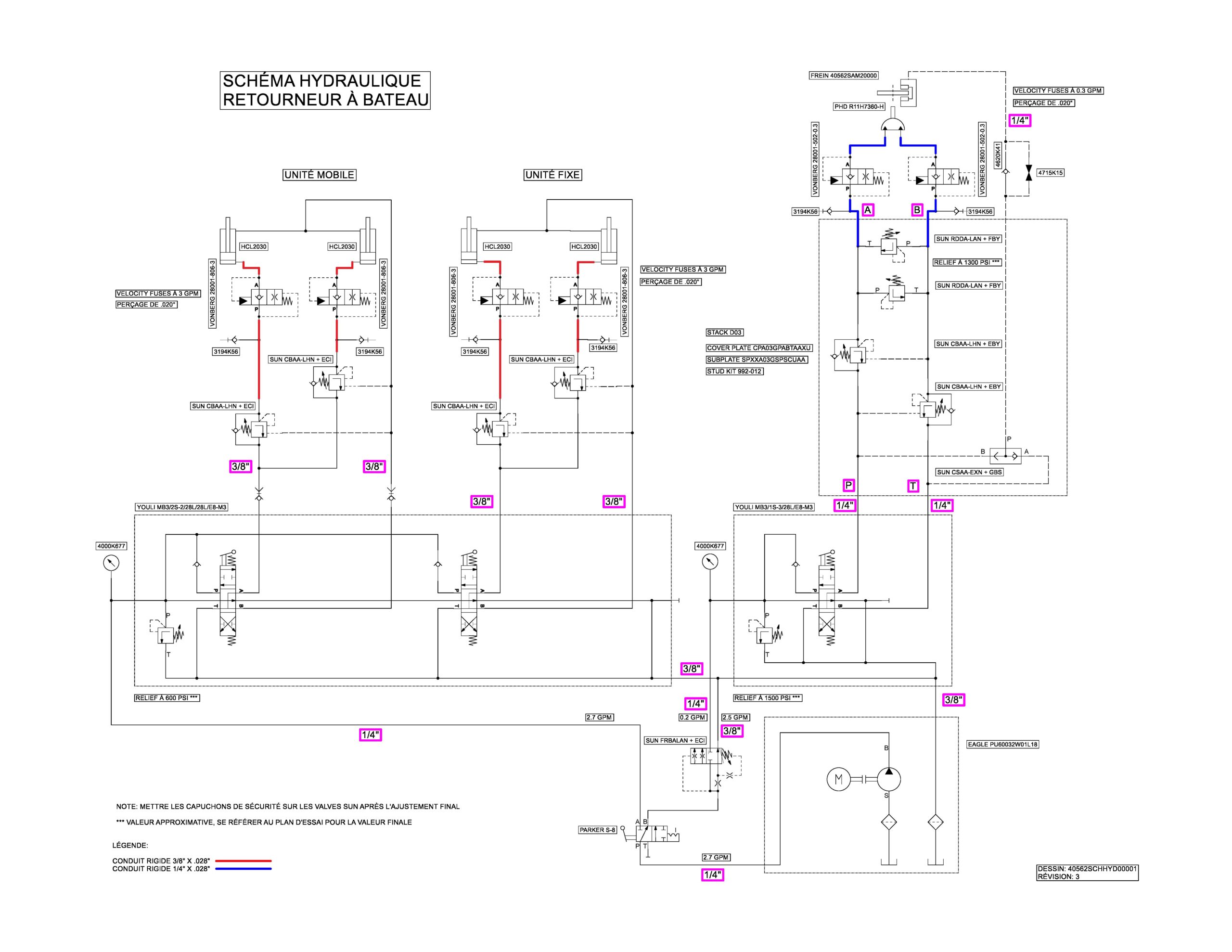
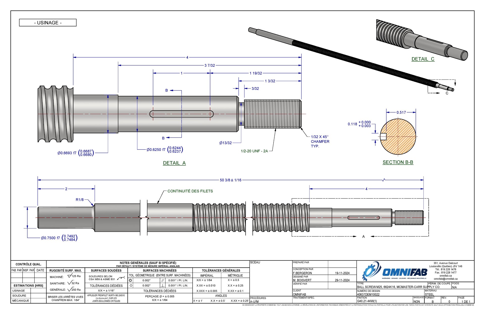
Here are a few examples of industrial drawings created by our teams.
Click on images to enlarge.
Different types of industrial drawings
To better meet the specific needs of each step in the design, manufacturing, and assembly process, various types of industrial drawings can be used. Each type of drawing serves a particular function and allows for clear and precise communication to different stakeholders (engineers, designers, technicians, etc.).
Preparatory drawings
Preliminary drawing
Initial representation to visualize and develop the general idea of a project.
Sketch
Typically hand-drawn, it captures basic ideas and early drafts.
Draft or outline
A slightly more refined version of a sketch, often used to give a clearer idea of proportions and shapes.
Template
Precise drawing, often full-scale, used in construction to visualize geometry and proportions.
Schematics
Principle diagram
Simplified representation that illustrates the functioning or principle of a system.
Kinematic diagram
Describes the movements and interactions between different parts of a mechanism.
Construction diagram
Shows the stages or details of constructing a project, including essential components.
Process and Instrumentation Diagram (PID)
Used in process engineering to show the flow of processes and control instruments.
Process Flow Diagram (PFD)
Represents the main flows of a process, like in the chemical industry, to show the progression of processes.
Pneumatic/Hydraulic diagram
Illustrations of systems using compressed air or fluids to transmit energy, showing components like cylinders, valves, pumps, and reservoirs, as well as their connections to clarify system operation.
Detailed Technical Drawings (or Manufacturing Drawings)
Assembly drawing
Shows the arrangement of all parts in an assembly and their relative positions.
Definition drawing (or detail drawing):
Specifies the exact details of each part (dimensions, materials, tolerances).
Exploded view drawing
Presents the different parts of an assembly separately, showing how they fit together.
Perspective drawing
A three-dimensional representation to visualize an object realistically.
For more details on manufacturing drawings, read our article on the subject!
The Title Block: Essential for Interpreting an Industrial Drawing
The title block is a fundamental element of an industrial drawing. Typically, it is a rectangular box located at the bottom of the drawing, below the object representation.
The title block provides essential project and piece information and plays a key role in archiving and organizing industrial drawings.
It may contain the following information:
- The name of the part or object
- The scale used for the representation
- The name of the draftsman or designer
- The type of projection used
- The date of the last drawing update
- Dimensional tolerance, if uniform for all measurements
Call on our industrial designers
Baselines: Another Crucial Element of Industrial Drawings
An industrial drawing uses different types of baselines to better represent all the features and details of an object. The use of each type of line must adhere to its function, as defined by convention.
Leader Lines
Leader lines are thin, short, continuous lines that connect dimension lines to the contour or details of the part they describe. They indicate the start and end of measurements without touching the contour lines.
Centerlines
Used to mark the axis of symmetry of a part or element, centerlines are typically represented by a fine, dashed line (composed of alternating long and short segments). They help center components and represent pivot points.
Section Cut Lines
These thick, continuous or dashed lines indicate where a cut is made in the drawing to reveal the inside of the part. They are often marked with arrows showing the direction of the section view.
Construction Lines
Construction lines are very light lines, often used for the initial sketch of a shape or dimension. They are not part of the final drawing and serve only as guides for placing other lines.
Visible Contour Lines
Visible contour lines are medium-weight, continuous lines that outline the visible edges of the part in the drawing. They give the primary visible shape of the object.
Hidden Lines
Hidden lines represent parts of the part that are not visible in the current view. They are represented by medium dashed lines.
Dimension Lines
Dimension lines are used to indicate the limits and dimensions of a segment. They consist of two arrows pointing in opposite directions, with the dimension placed between them. Each arrow points to a reference line. Dimension lines are drawn with a fine, continuous line.
Reference Lines
Reference lines connect a note or reference to a specific part of the drawing. They help clarify additional details or specific instructions regarding certain parts of the piece. They are usually represented by a fine line with an angle of 30 to 45 degrees. Often, an arrowhead helps specify which element of the drawing the note refers to.
Hatching Lines
Used in section views, hatching lines show the surfaces of the part that have been cut to reveal the inside. Represented by fine, parallel lines, they help differentiate materials and cut sections in an exploded view.
Types of Projections
The different types of projections below are essential in industrial drawing, as each allows for the communication of specific information clearly and precisely.
Multiview Projection
This method involves representing an object from multiple different angles to provide a complete view. Typically, front, side, and top views are used. Each view is placed on orthogonal planes that are perpendicular to each other. This allows for accurate description of the object's dimensions and geometry in specific directions.
Axonometric Projection (Exploded View)
Axonometric projection is a three-dimensional projection that represents the object without considering perspective, meaning the dimensions are maintained at a uniform scale along all three axes.
Isometric Projection
Isometric projection is a type of axonometric projection where the three axes of the object (length, width, and height) are represented at equal angles of 120° between them. The dimensions along these axes are to scale, providing a more "realistic" three-dimensional representation of the object.
Oblique Projection
Oblique projection is a method where the object is projected onto a plane such that one of its faces is shown in a frontal view while the other dimensions are projected obliquely.
The Registration of an Industrial Drawing
Industrial design registration protects the original visual characteristics of a finished object, such as its shape, configuration, motifs, decorative elements or any combination of these.
In Canada, industrial designs are administered by the Canadian Intellectual Property Office (CIPO). Registration of an industrial design grants exclusive rights for a period of 10 years from the date of registration.
Choose Our Industrial Drawing Service
In summary, an industrial drawing is a technical representation of an object or system, created according to established standards, to accurately present its main characteristics for manufacturing.
At Omnifab, we can provide you with various types of essential drawings for your projects:
- Factory layouts
- Hydraulic schematics
- Pneumatic schematics
- Engineering plans
- Preliminary plans
- Workshop drawings
- Machining
- Welded parts
- Sheet metal
- Assembly
- Cast parts (raw casting)
Contact us to learn more!
