In life, some things are inseparable, like yin and yang, day and night, Batman and Robin — to name a few. Among the things that often come in pairs, there’s also the electric motor and its loyal companion: the speed reducer.
Unfortunately, despite its crucial role in numerous industrial applications, the mechanical reducer isn’t widely known to the public. That’s why our experts in speed reducer sales and repair have prepared this handy guide about this equipment, often called a “gearbox.”
In the following paragraphs, you’ll find plenty of useful information about mechanical speed reducers.
Mechanical Speed Reducer: Definition
A mechanical speed reducer is a device designed to convert the torque and speed of an upstream electric motor to meet the drive requirements of an application.
The term “mechanical” emphasizes that this type of reducer uses mechanical components, such as gears, worm screws, belts, or chains, to modify the speed and torque transmitted to the final system. Unlike electronic or hydraulic reducers, mechanical reducers rely on the physics of forces and rotational movements to adjust transmission parameters without using electricity or hydraulics.
The Role of the Speed Reducer
As its name suggests, the primary role of the speed reducer is to reduce the rotation speed from an electric motor. However, it also plays the crucial role of increasing the torque applied to the load.
In other words, the mechanical reducer’s function is to adapt a motor’s speed and torque to match the specific requirements of a machine or equipment. This allows the motor to operate efficiently at higher speeds while ensuring the connected machine runs at optimal speed with sufficient force to perform its task.
How Does a Mechanical Speed Reducer Work?
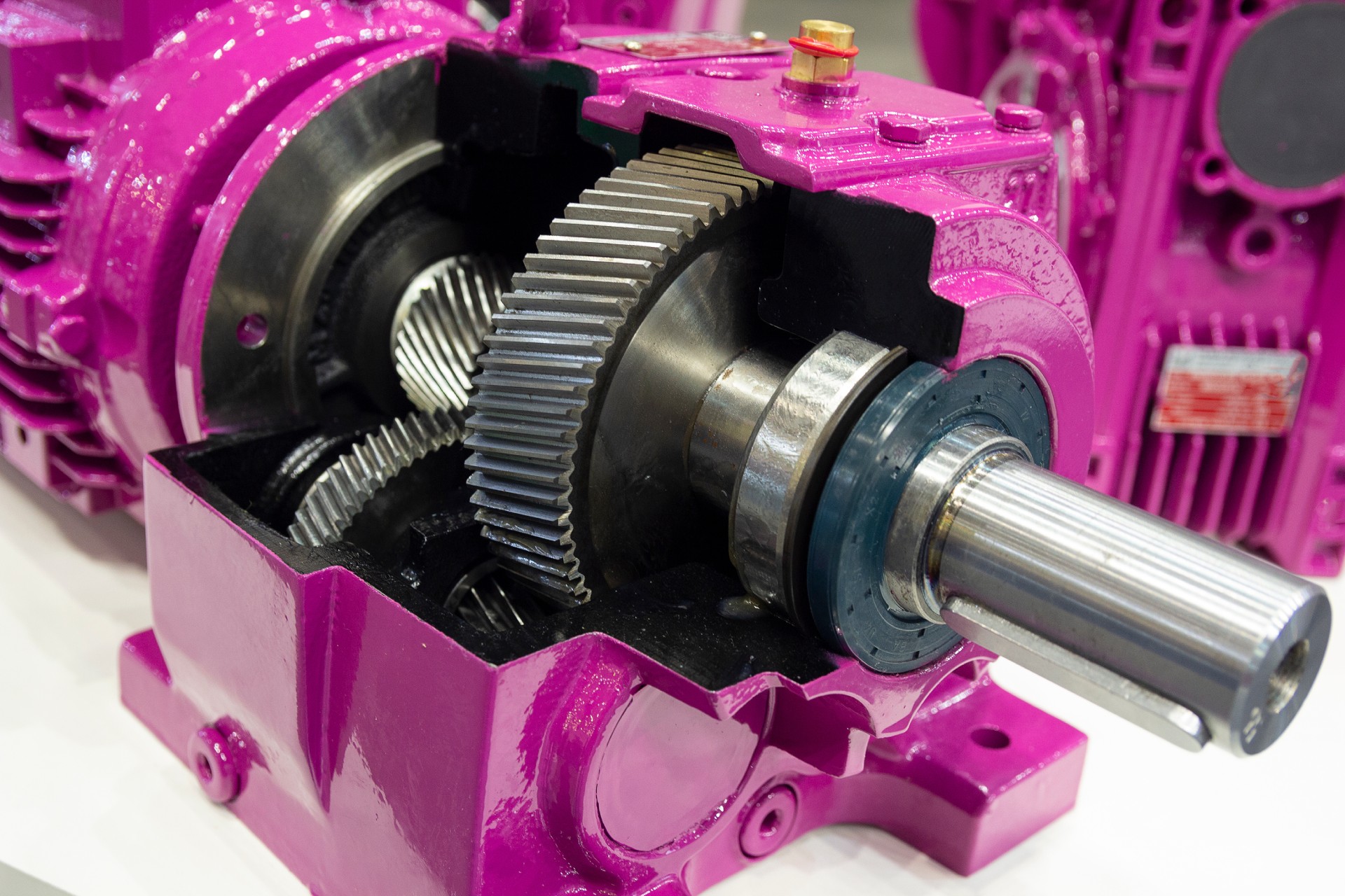
A speed reducer decreases a motor’s rotation speed mainly through sets of gears of different sizes, hence the frequently used term “gearbox.” When a smaller pinion (driven by the motor) engages a larger gear, each complete rotation of the pinion results in a partial rotation of the larger gear, thereby reducing the output speed compared to the input speed.
The number of teeth on each gear also plays a crucial role in this process: the more teeth the output gear has relative to the input gear, the greater the speed reduction. This gear ratio, also known as the speed ratio, measures how many times the speed is divided.
By using multiple successive gear trains, a reducer can further increase this reduction and transfer torque, measured in Newton meters (Nm), by generating increased rotational force at the output. This torque increase allows the reducer to transmit high power, essential for driving heavy loads or providing optimal rotational effort for various industrial applications.
Discuss Your Needs with a Speed Reducer Specialist
Examples of Mechanical Reducer Applications
The following examples illustrate the versatility of speed reducers, which can adapt to a wide range of applications.
1 – Industrial Conveyors
In factories and distribution centers equipped with conveyors, they regulate belt movement to smoothly transport heavy or bulky loads.
2 – Winches, Cranes, and Other Lifting Equipment
In lifting systems, they control rotation speed to raise and lower loads precisely and safely while increasing lifting force.
3 – Elevators and Escalators
In lifts, elevators and moving stairways, they ensure controlled speed and smooth starts, improving comfort and safety for users.
4 – Food Processing Machines
In food processing equipment (such as grinders or industrial mixers), they allow speed and blade force adjustments to chop, mix, or knead effectively, depending on the specific food requirements.
5 – Industrial Printers and Presses
In printing and industrial press machines, they ensure controlled roller movement, guaranteeing consistent throughput and uniform print quality while providing sufficient torque to drive large paper loads.
6 – Industrial Pumps
In industrial pumping systems, particularly for viscous liquids or chemicals, reducers control the pumping speed to avoid turbulence and adjust the flow rate as needed while delivering the torque required to overcome fluid resistance.
Types of Mechanical Speed Reducers
There are several types of mechanical speed reducers. Below are the main ones, with a brief description.
Spur Gear Reducer
This type of reducer uses spur or helical gears to transmit motion efficiently. Spur gears are simple and economical but produce more noise at high speeds. Helical gears, on the other hand, are quieter and provide smoother transmission, making them suitable for high-precision industrial applications.
Worm Gear Reducer
It consists of a worm screw paired with a helical gear, enabling significant speed reduction in a compact space. This type of reducer offers self-locking capabilities in some cases (movement cannot be reversed) and is often used in applications requiring added security, such as elevators and some handling equipment.
Planetary Reducer
In a planetary reducer, several satellite gears rotate around a central pinion (the sun) inside a ring gear. This system provides high reduction in a compact format and is highly robust. It’s commonly used in industrial robots, power tools, and wind turbine transmissions.
Parallel Shaft Reducer
These reducers consist of gears (often spur or helical gears) mounted on parallel shafts. They are simple and versatile, making them suitable for moderate reduction applications in tight spaces.
Epicyclic Train Reducer
Similar to the planetary reducer, it includes multiple rotation axes with concentric gears. This type of reducer is very compact and offers high reduction and torque capacity.
Bevel Gear Reducer
Using bevel gears to change motion direction by 90 degrees, bevel reducers are often used in systems where input and output shafts must be perpendicular, such as conveyors and machine tools.
Cycloidal Reducer
This reducer uses a cycloidal disc to reduce speed and increase torque. It is particularly robust and compact, with a design that distributes the load over multiple contact points. It’s commonly found in heavy-duty and high-precision applications such as industrial robots.
Servo Reducer
A servo reducer is a type of speed reducer specifically designed to be used with servo motors to enhance system performance in tasks requiring fast response and precise control.
Classification of Reducers by Input and Output Shaft Orientation
In addition to their type, mechanical reducers can also be classified into four categories based on the orientation of the input (motor shaft) and output shafts.
- Offset shafts – The motor shaft is offset from the output shaft.
- Coaxial shafts – The motor shaft is aligned with the output shaft.
- Right-angle shafts – The motor shaft is perpendicular to the output shaft.
- Parallel shafts – The motor shaft is parallel to the output shaft.
This classification is crucial when selecting a reducer based on the application’s specific requirements, mounting conditions, and desired compactness.
The Importance of Mechanical Reducer Maintenance
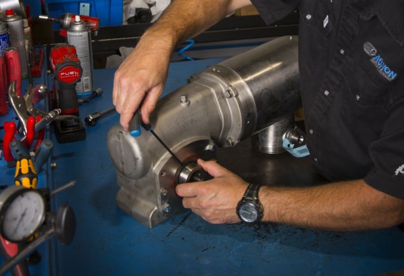
Proper maintenance of mechanical speed reducers is crucial to ensuring long service life and optimal efficiency. Regular maintenance, including lubricant checks, seal inspections, internal component inspection, and temperature and vibration monitoring, is essential to prevent breakdowns and avoid costly repairs.
Omnifab: A Trusted Name in Speed Reducers in Quebec
If you have further questions about speed reducers (models, top brands, etc.) or need a technician capable of repairing them, the Omnifab team is your best resource.
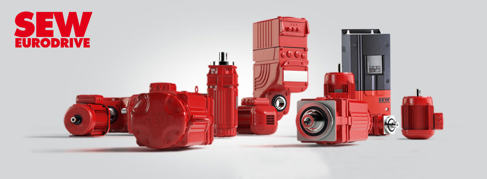
You’ll also be pleased to know that our inventory includes reducers from well-known brands such as Nord Gear and SEW Eurodrive.
Contact us now, and we will promptly mobilize the necessary resources to provide you with the best possible service.


