A mechanical transmission can be defined as a set of components or mechanisms used to transfer energy or motion from one part of a machine to another.
Transmissions can include elements such as gears, belts, chains, shafts, and couplings, which allow for modification in parameters such as speed, torque, direction, or type of motion (linear or rotary) to meet the specific requirements of a given application.
In the following paragraphs, learn more about the main types of transmission used in industrial machinery and equipment.
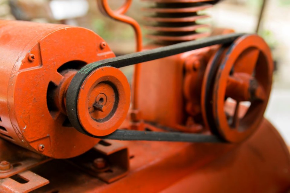
Belt and Pulley Transmission
The belt and pulley mechanism transmits rotary motion between two or more pulleys that are spaced apart. The motion is initiated by a driving pulley that rotates one or more driven pulleys via a belt made of rubber, polyurethane, reinforced fibers or other materials. Each pulley makes contact with the belt.
Important Concepts
- With this mechanism, the direction of rotation of pulleys on the same side of the belt is identical, but if pulleys are on the outside of the belt, their direction of rotation will be reversed. The direction of rotation will also be reversed if the belt is crossed.
- It is possible to orient the pulleys perpendicular to each other, allowing rotation along different axes.
- To increase the belt’s grip and reduce the risk of slippage, it’s important to choose the appropriate materials and consider factors such as pulley type and belt type. Here are some belt types commonly used in transmissions:
- Flat belt: Simple and economical, but can slip, resulting in a loss of power.
- V-belt: Provides better grip than the flat belt due to its V-shape, thus reducing slippage.
- Timing (or synchronous) belt: Has teeth that mesh with pulleys, virtually eliminating slippage, ideal for precise synchronization.
Advantages
- Each pulley of the system can be the driving or driven member (reversible mechanism).
- The rotation speed can be adjusted by changing the diameter of the pulleys.
- Allows the rotation axis to be changed.
- Relatively silent mechanism.
- Ensures smooth motion due to the elasticity of the belt.
- Capable of higher speeds than chain and sprocket transmission systems.
- Unlike chains, belts do not require lubrication.
Disadvantages
- Possible loss of efficiency if the belt slips on the pulleys.
- Pulleys and belts are sensitive to temperature extremes (changes belt flexibility), wear and dirt.
- Belt tension needs be adjusted periodically.
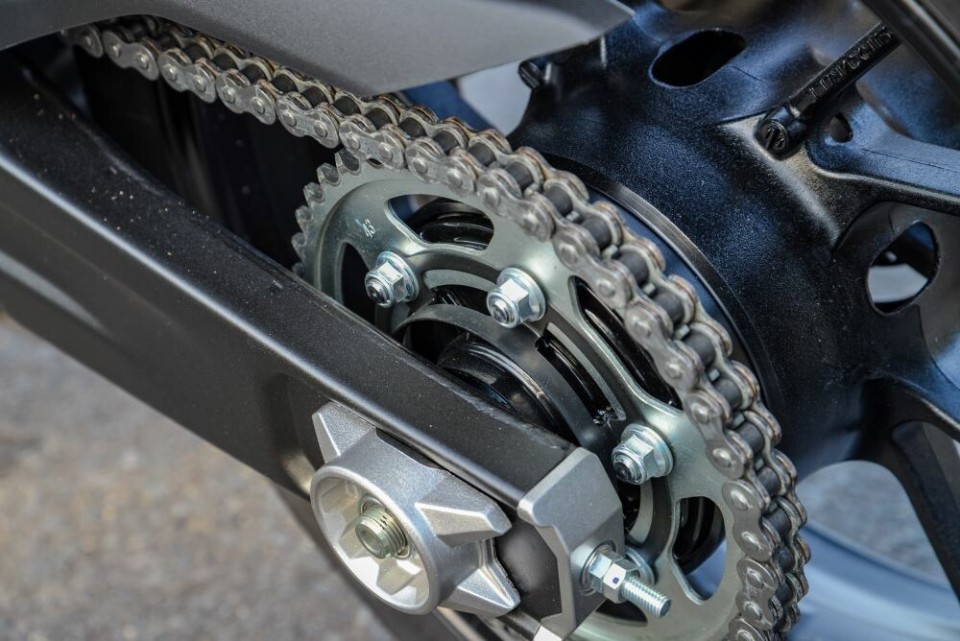
Chain and Sprocket Transmission
The chain and sprocket mechanism transmits rotational motion between two or more spaced toothed wheels (sprockets). The motion is initiated by a driving sprocket, which rotates one or more driven sprocket via a chain. Each sprocket is in contact with the chain so that its teeth fit sequentially into the chain links.
This type of transmission is commonly used on bicycles and many types of motorcycles.
Important Concepts
- With this mechanism, the sprockets on the same side of the chain have the same direction of rotation. However, if the sprockets are on the outside of the chain, their direction of rotation is reversed from those on the inside.
Advantages
- Each sprocket of the system can be the driving or driven member (reversible mechanism).
- Speed can be adjusted by changing the diameter of the sprockets.
- Teeth and links virtually eliminate the risk of slippage.
- High acceleration of the driving sprocket.
- Chains are generally stronger than belts.
- Chain length can be easily adjusted by site maintenance personnel, unlike belts.
Disadvantages
- Chain must be lubricated regularly.
- Chain tension must be adjusted periodically (risk of derailment if tension is too low).
- Sprocket axes must be perfectly parallel.
- Noisy system, likely to generate vibrations.
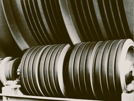
Friction Wheel Transmission
The friction wheel mechanism transmits rotational motion from a driving wheel to one or more driven wheels through direct contact. The system relies on friction between the wheels which must maintain continuous engagement to function effectively.
This type of mechanism is often used to drive ball mills.
Important Concepts
- In this mechanism, the direction of rotation of the wheels is reversed from one wheel to the next. In other words, for the direction of rotation of the drive wheel and the last wheel in a system to be the same, the system must contain an odd number of wheels.
- The axis of the wheels can be oriented to switch between vertical and horizontal rotation.
- The choice of wheel materials must ensure sufficient grip to prevent slippage.
Advantages
- Each wheel in the system can be the driving or driven member (reversible mechanism).
- Rotational speed can be adjusted by changing the diameter of the wheels.
- Relatively quiet system.
- Generally inexpensive type of transmission.
- Mechanism provides natural protection against jamming, overloading, or impact because it slides rather than breaks.
- The wheel parallel alignment can be slightly altered to force the system counterpart to deviate (e.g. paper strip, sheet metal, cardboard, membrane).
Disadvantages
- Subject to loss of efficiency due to slippage (wear, dirt, etc.).
- Requires precise assembly.
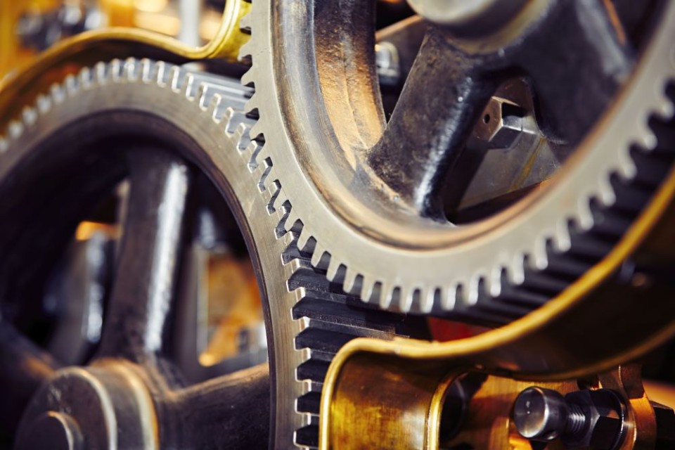
Gear Transmission
The gear transmission mechanism (sometimes referred to as a cogwheel mechanism) transmits rotational motion between two or more gears whose teeth engage (mesh) in succession. The drive gear initiates the motion and transmits it to the driven gears.
This type of system is particularly useful for transmitting motion between closely spaced parts.
Important Concepts
- In this mechanism, the direction of rotation of the gears is reversed from one to the next. As with friction gear systems, the system must contain an odd number of gears in order for the direction of rotation of the driving gear and the last gear in the system to be the same.
- Special types of gears can be used:
- Spur gears: The teeth are parallel to the axis of rotation. They are used for high-power transmissions.
- Helical gears: The teeth are inclined to the axis, providing quieter, smoother transmission.
- Bevel gears: Used to change the direction of rotation by 90° (from vertical to horizontal or vice versa).
Advantages
- Each gear of the system can be the driving or driven member (reversible mechanism).
- Rotational speed can be adjusted by changing the diameter of the gears.
- The system can be very small (like a watch).
- Very precise system.
Disadvantages
- Can be noisy and generate vibrations.
- Requires periodic cleaning (highly sensitive to dirt) and lubrication.
- Requires very precise adjustment to ensure adequate contact between teeth.
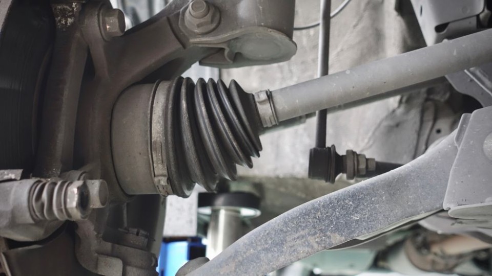
Shaft and Coupling Transmission
The shaft and coupling transmission mechanism transmits rotary motion between two or more mechanical components, often over greater distances than other transmission types. This system uses a shaft (rigid or flexible) to connect the components and a coupling to transfer motion between the shafts. The drive shaft is the one that initiates motion and transmits it to the driven shafts.
This type of system is particularly useful for transmitting motion between distant parts or for accommodating misalignment between components.
Important Concepts
- Shafts transmit rotary motion either rigidly (directly and without bending) or flexibly (bending and adapting to curved or misaligned paths), depending on the type of shaft used.
- Couplings connect shafts together to compensate for misalignment or vibration. Here are the main types:
- Rigid coupling: Provides a solid connection between shafts, transmitting motion without play.
- Flexible coupling: Accommodates angular or axial misalignment between shafts, reducing vibration and mechanical stress.
- Friction coupling: Transmits motion by friction, often used in systems that require controlled slip for overload protection.
Advantages
- Can transmit motion over long distances or between misaligned components.
- Couplings allow easy disassembly for maintenance or part replacement.
- Flexible couplings can absorb vibration, providing protection for system components.
Disadvantages
- Assembling this type of transmission can be complex, requiring precise alignment of components to prevent imbalance.
- Couplings can wear over time, requiring regular monitoring and maintenance.
- With rigid shafts, excessive forces may lead to deformation or mechanical failure.
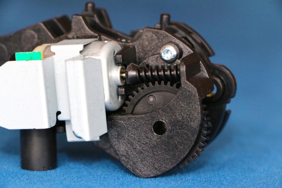
Worm and Gear Transmission
The worm-and-gear transmission mechanism converts rotary motion into perpendicular rotary motion while reducing speed and increasing torque. This system consists of a worm (a screw with a helical thread) that meshes with a gearwheel oriented perpendicularly. As the worm turns, it drives the gear to rotate at a reduction ratio defined by the number of teeth on the gear.
This type of system is particularly useful for applications requiring significant speed reduction and precise motion control.
Important Concepts
- The reduction ratio of a worm gear determined by the number of worm threads and the number of gear teeth. When the worm has fewer threads (usually only one) compared to the number of teeth on the gearwheel, it significantly reduces the output speed while increasing the torque.
- The mechanism can be self-locking, preventing the gearwheel to turn the worm unless the motor is engaged. This is useful in applications where reciprocating motion under load is to be prevented, such as in lifting equipment.
- Different types of worms can be used in this type of gear:
- Single thread worm: The worm has a single thread that meshes with the gear to achieve maximum speed reduction.
- Worm with two or more threads: Allows the gear to move faster with a compromise in torque reduction.
Advantages
- Significantly reduces speed while increasing torque, making it ideal for hoists or conveyors.
- In some configurations, the system prevents reverse movement (self-locking), enhancing safety for load holding applications.
- This mechanism can transmit high forces, even when it is relatively small.
Disadvantages
- High friction between worm and gear can result in significant energy loss, reducing overall system efficiency.
- Constant contact between the worm and gear can lead to rapid surface wear, requiring regular maintenance.
- Due to high friction, this type of mechanism generates a significant amount of heat, demanding cooling or proper lubrication.
- Requires accurate alignment of gear teeth with worm pitch, potentially increasing manufacturing costs.
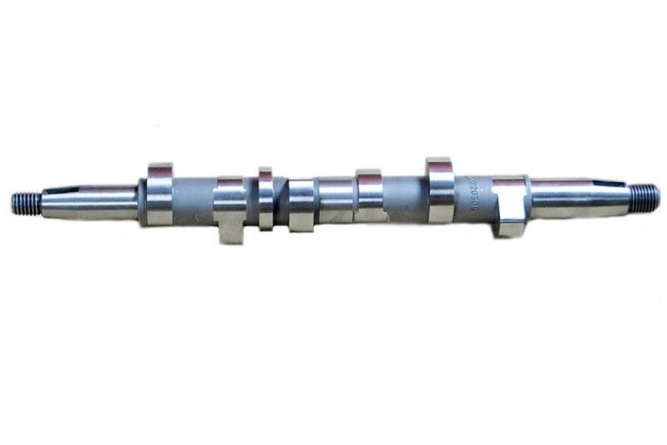
Cam and Lever Transmission
The cam and lever transmission mechanism converts rotary motion into linear or reciprocating motion. This system uses a cam, an irregularly shaped part mounted on a rotating shaft (hence the name camshaft), to move a lever or rod along a predefined profile. As the cam rotates, it pushes or pulls the lever, resulting in a controlled motion.
This type of system is particularly useful in applications that require repetitive or complex movements, such as internal combustion engines or machine tools used in machine shops.
Important Concepts
- Cam rotation produces linear or oscillating motion of the lever, depending on the cam profile (shape) and lever axis. The movement of the lever can be very precise and is determined by the contour of the cam.
- Several types of cams can be used in this type of transmission:
- Cylindrical cam: A cylinder with a helical profile that moves a lever perpendicular to its axis. Often used to create complex translational motion.
- Disk cam: A circular disk with an irregular contour. Motion is transmitted to a lever that follows the contour, often used to create reciprocating motion.
- Roller cam: Used to reduce friction between the cam and lever, increasing the durability and accuracy of the system.
Advantages
- Allows the creation of complex, precise movements that are adjustable according to the cam profile.
- A relatively simple system with few moving parts, making it reliable and easy to maintain.
- Can be used in a wide variety of applications, from sewing machines to automobile engines.
Disadvantages
- Direct contact between cam and lever can result in surface wear requiring regular maintenance.
- Lever movement is completely dictated by the cam profile, limiting application flexibility. Any change in motion requires a different cam profile.
- Intermittent contact between cam and lever can cause noise and vibration, especially at high speeds.
Omnifab shares its transmission expertise with you
In summary, all of these types of mechanical transmissions can be used to transmit motion in industrial equipment. When designing a custom machine, our designers consider criteria such as the space available, the type of motion to be transmitted, the desired speed, and the force required.
It’s also important to remember that these various types of transmissions require regular inspections and periodic maintenance to ensure smooth operation and avoid unexpected downtime. For this, you can rely on our machinery service and maintenance team.
Finally, if you encounter problem with an industrial gearbox, our Machinery Repair team is there for you! They work closely with our machining department, which has the capacity to produce replacement parts in unbeatable lead times.
In short, Omnifab is your best resource for all your industrial transmission needs.